Preamble
In this article, we are looking at a beginner’s project related to Arduino. This project includes two developments: the basic blink Arduino Uno project and the analog input project. To learn more about applying to the world of Arduino, I invite you to review my article on this matter: Introduction for Arduino projects for beginners. The blog is a starter kit project for beginners.
What is Arduino Uno?
Arduino Uno is the numerous popular board in the Arduino family. It is the most board used; it has the widest documentation on the market.
Around the web, tons of projects, tutorials, and forums can help any beginners get started around the web.
It is recommended that Arduino Uno be a great starter.
The Arduino Uno componnents
Here are the Arduino Uno component and its function.
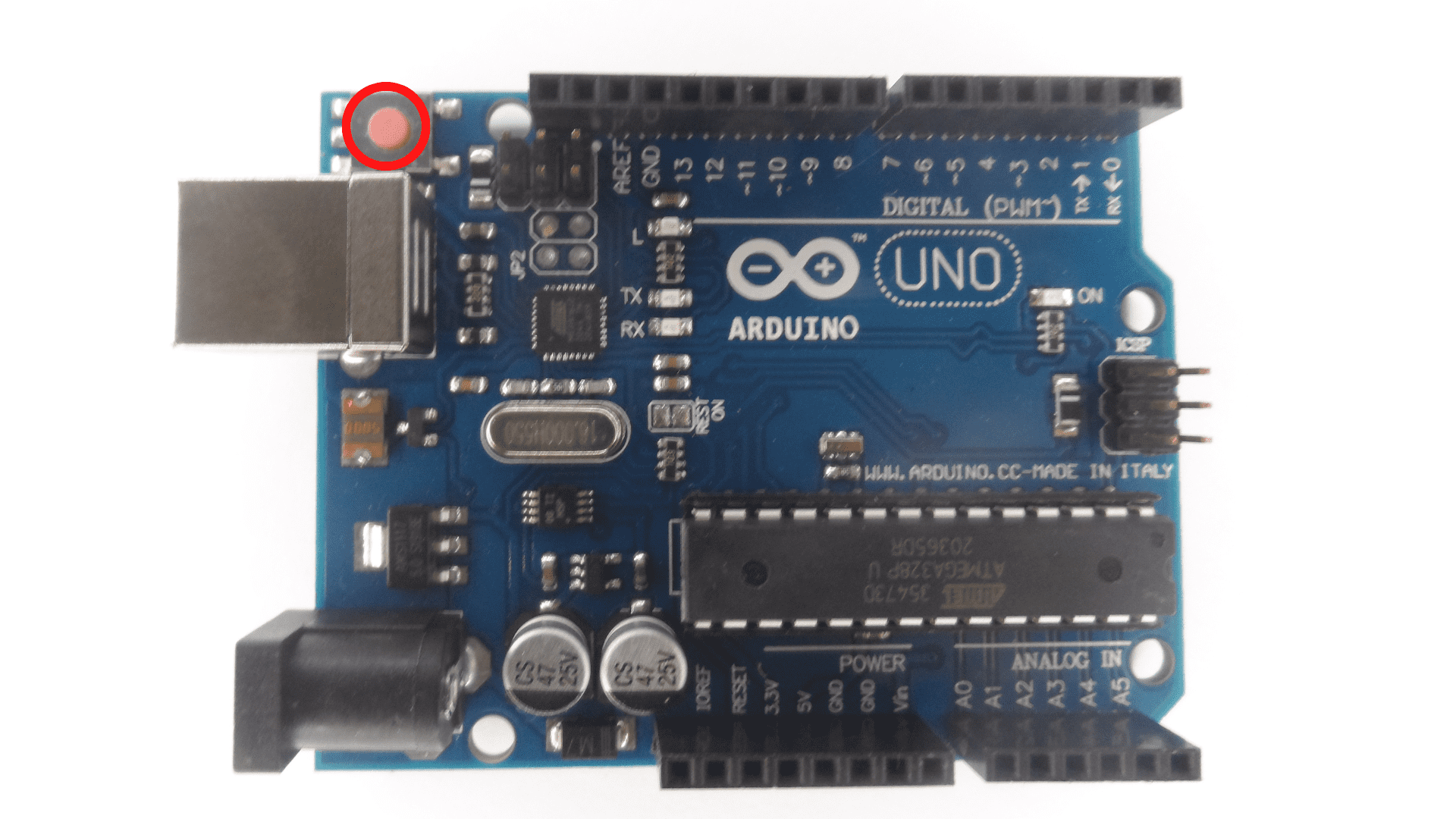
1- Reset ButtonThe reset button resets the code itself, which means it starts from the beginning. The reset button does not reset the board itself.
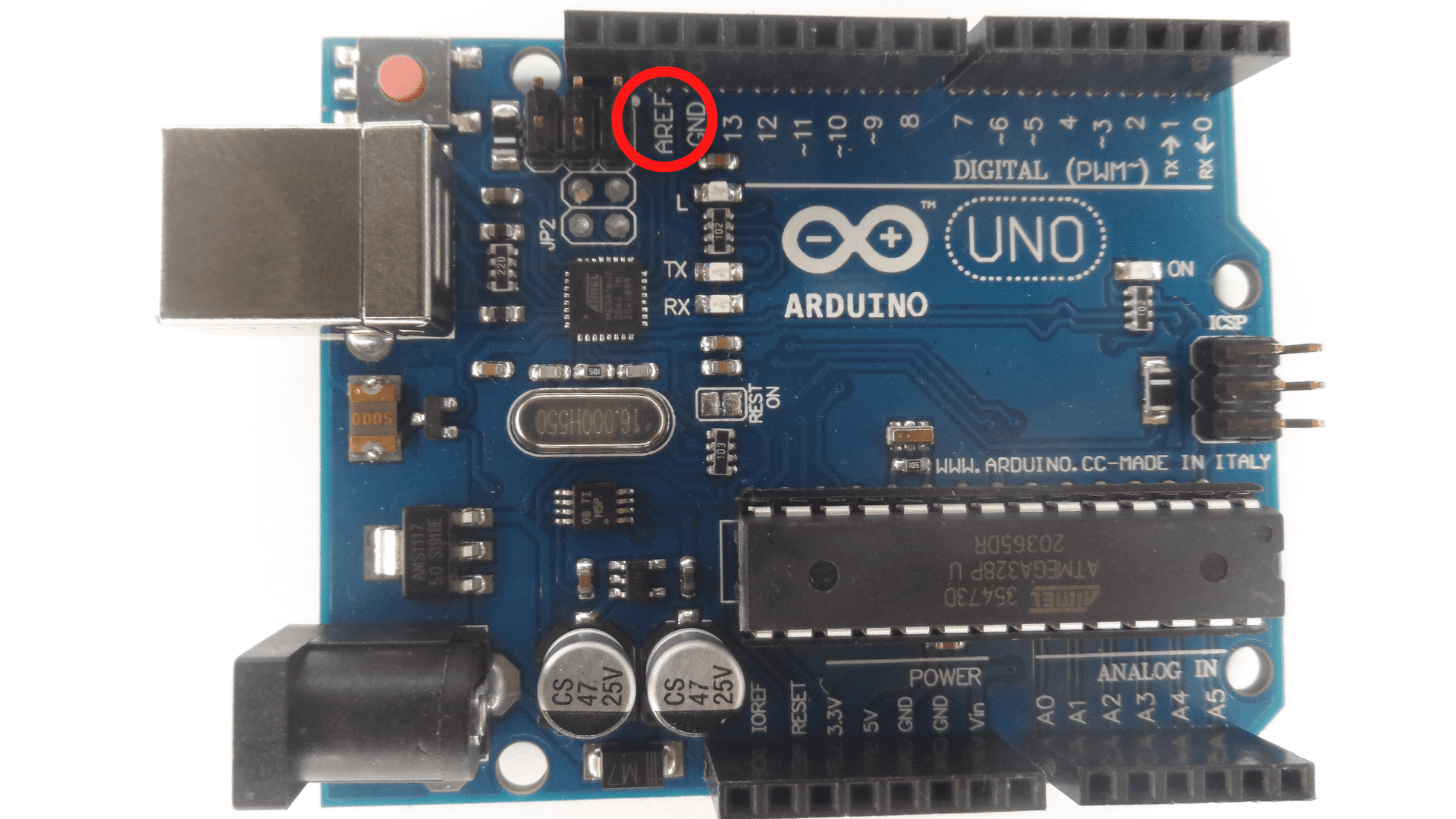
 2-AREF means analog reference. The user of the Arduino board uses AREF to set an external reference voltage.
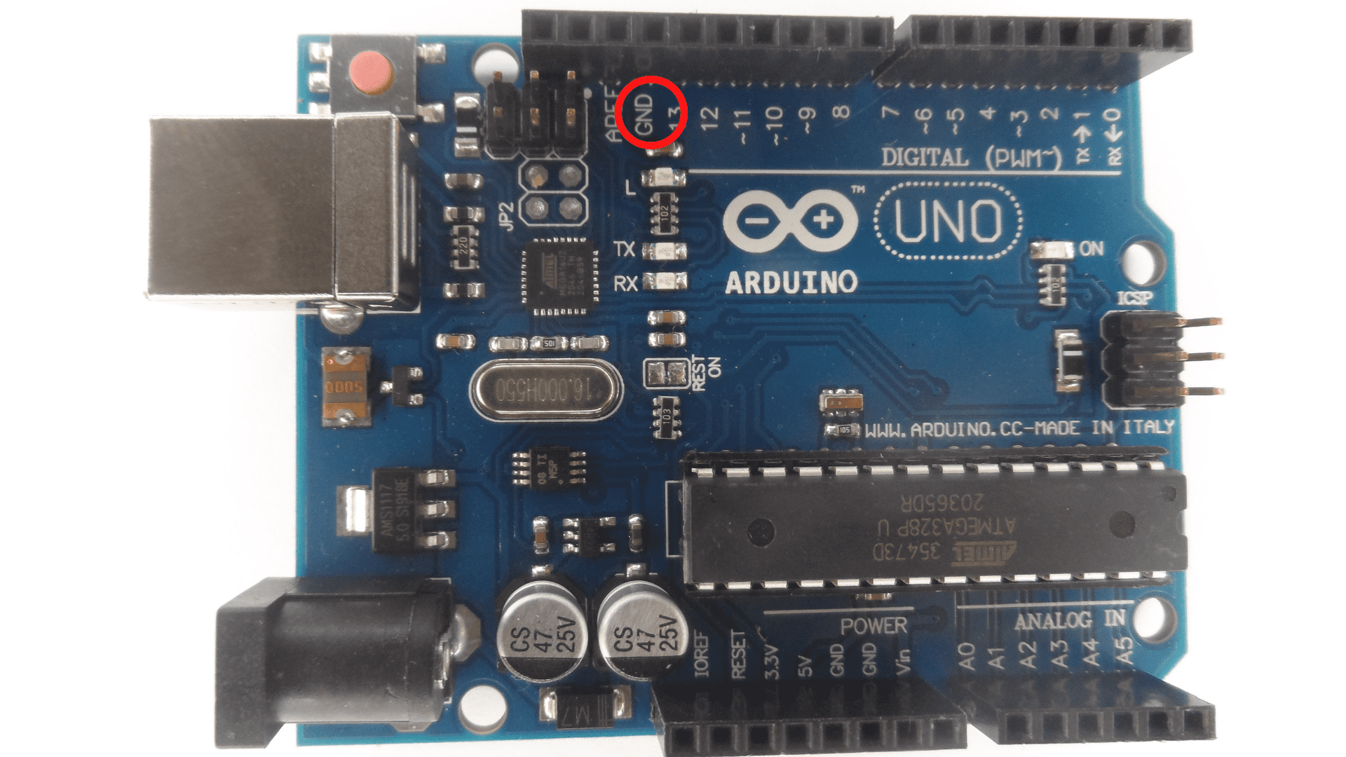
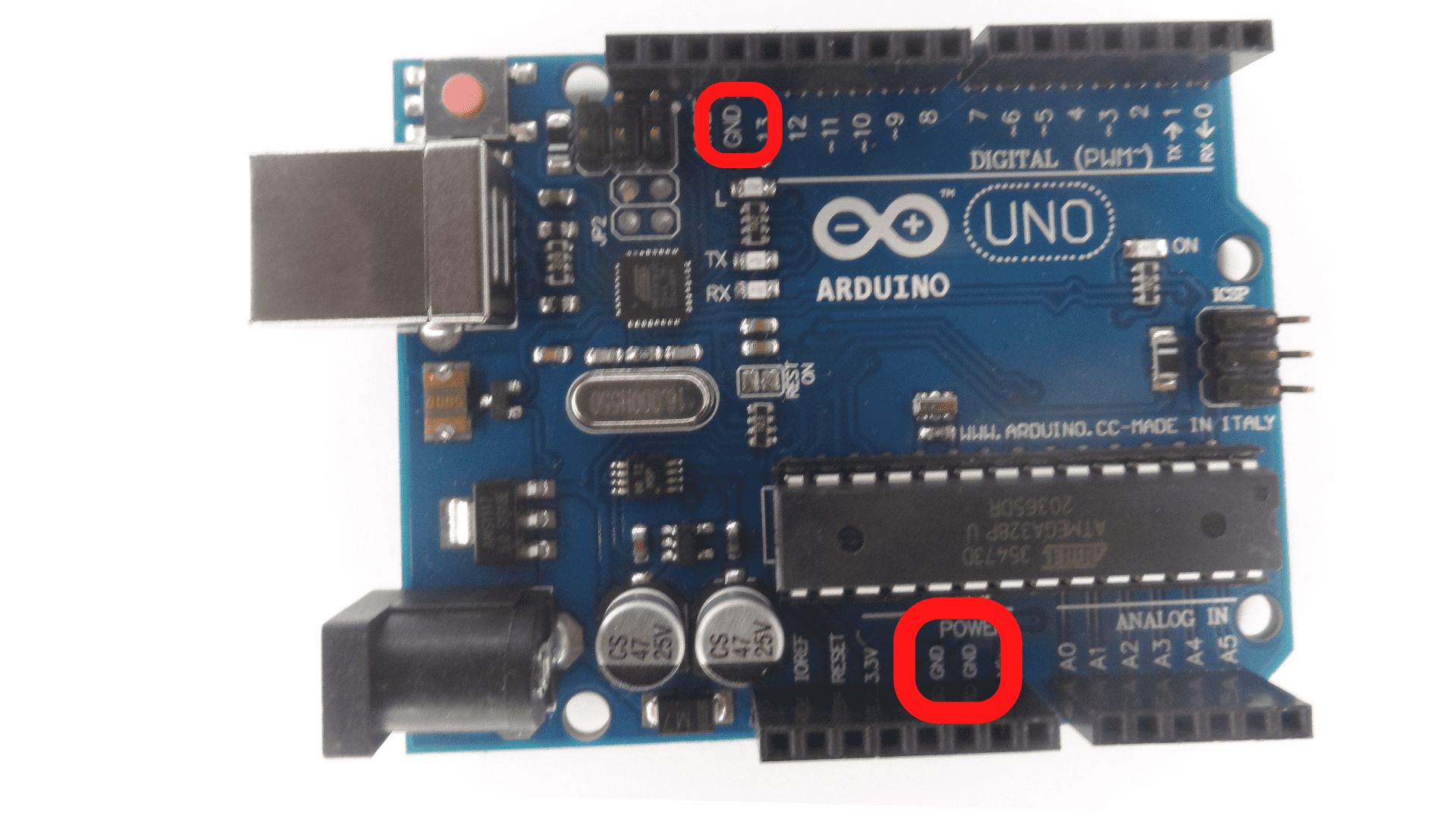
 3- Ground pin
The ground pin is a type of electrical connector. It provides an earth ground for the circuit and has a fundamental safety reason.
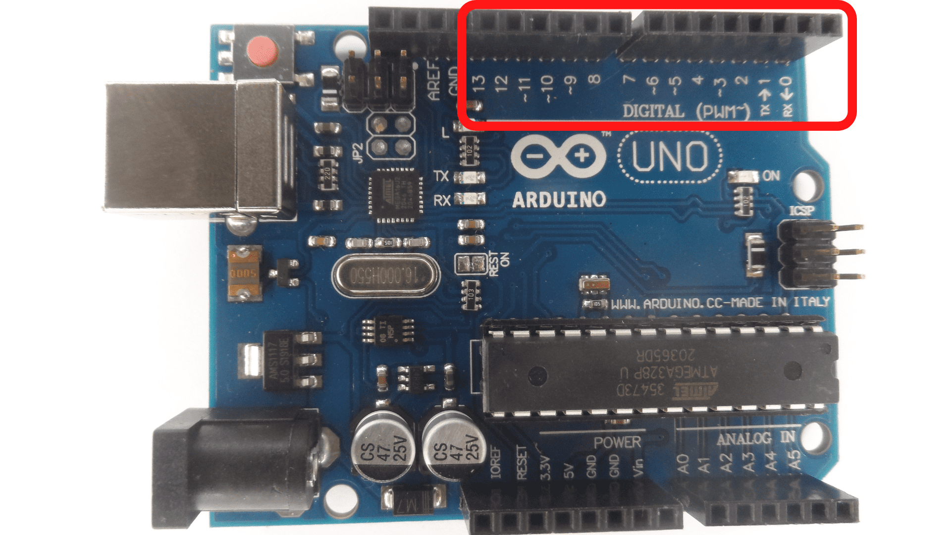
 4- Digital Input/OutputThere are 14 pins from 0 to 13. They are for digital input and output uses.
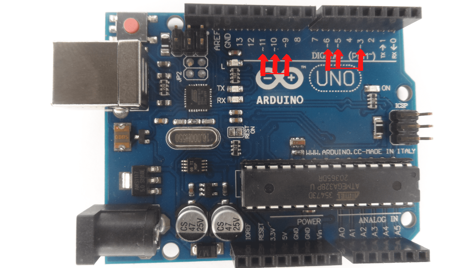
 5 -PWM The pin symbols ~ can simulate analog output.
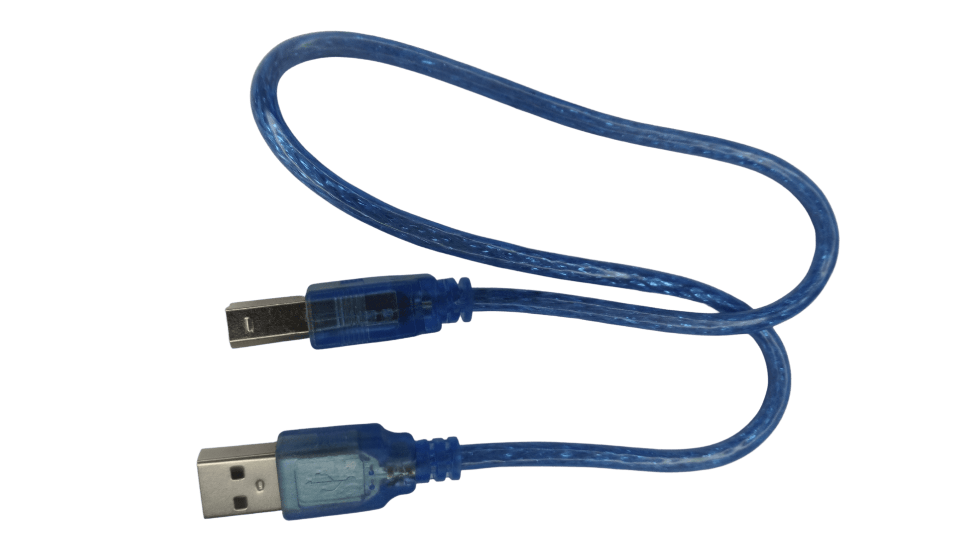
 6- USB connection
The USB is for powering up the Arduino and uploading sketches.
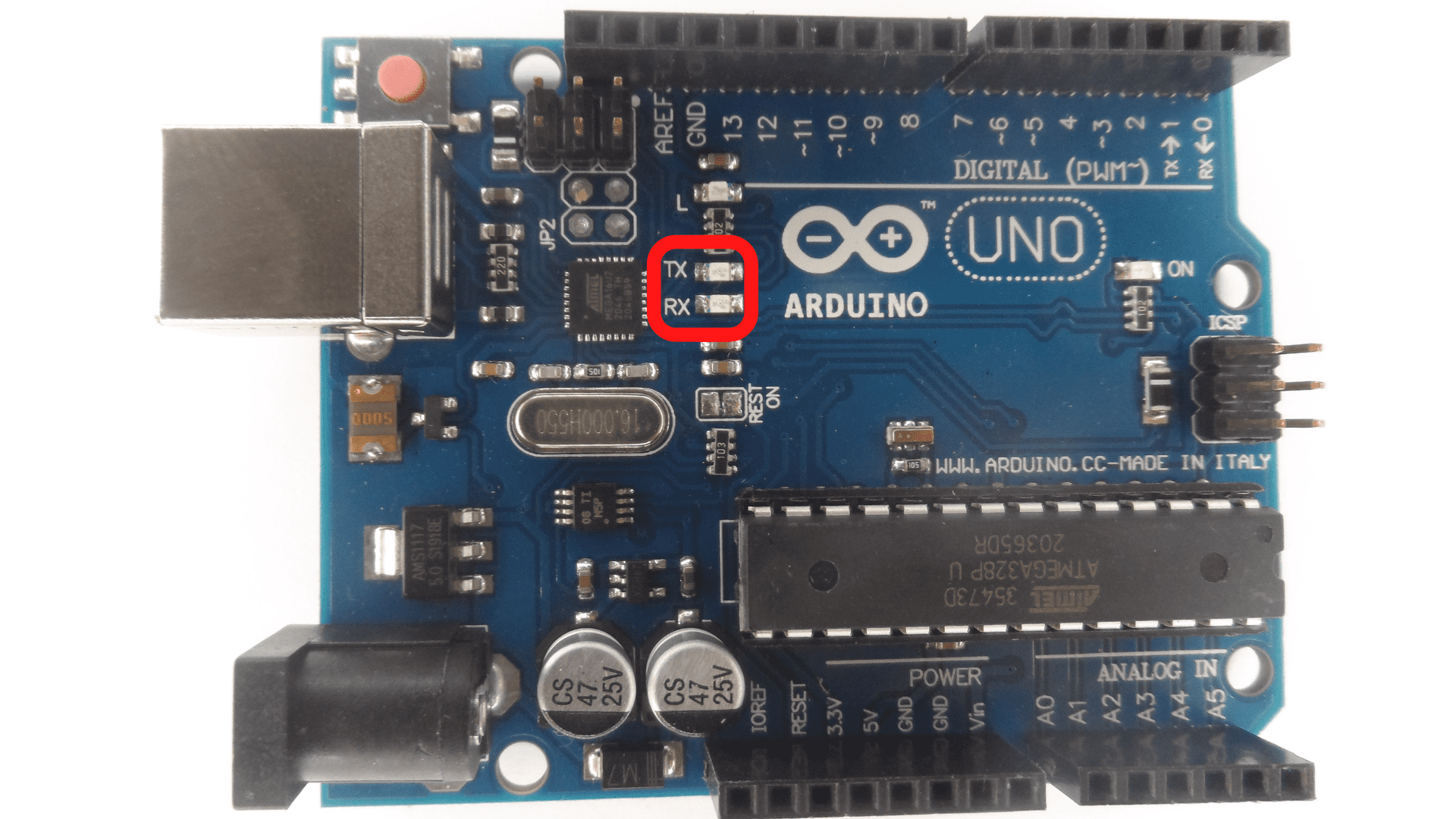
 7- TX / RXReceive and transmit the data indication LEDs.
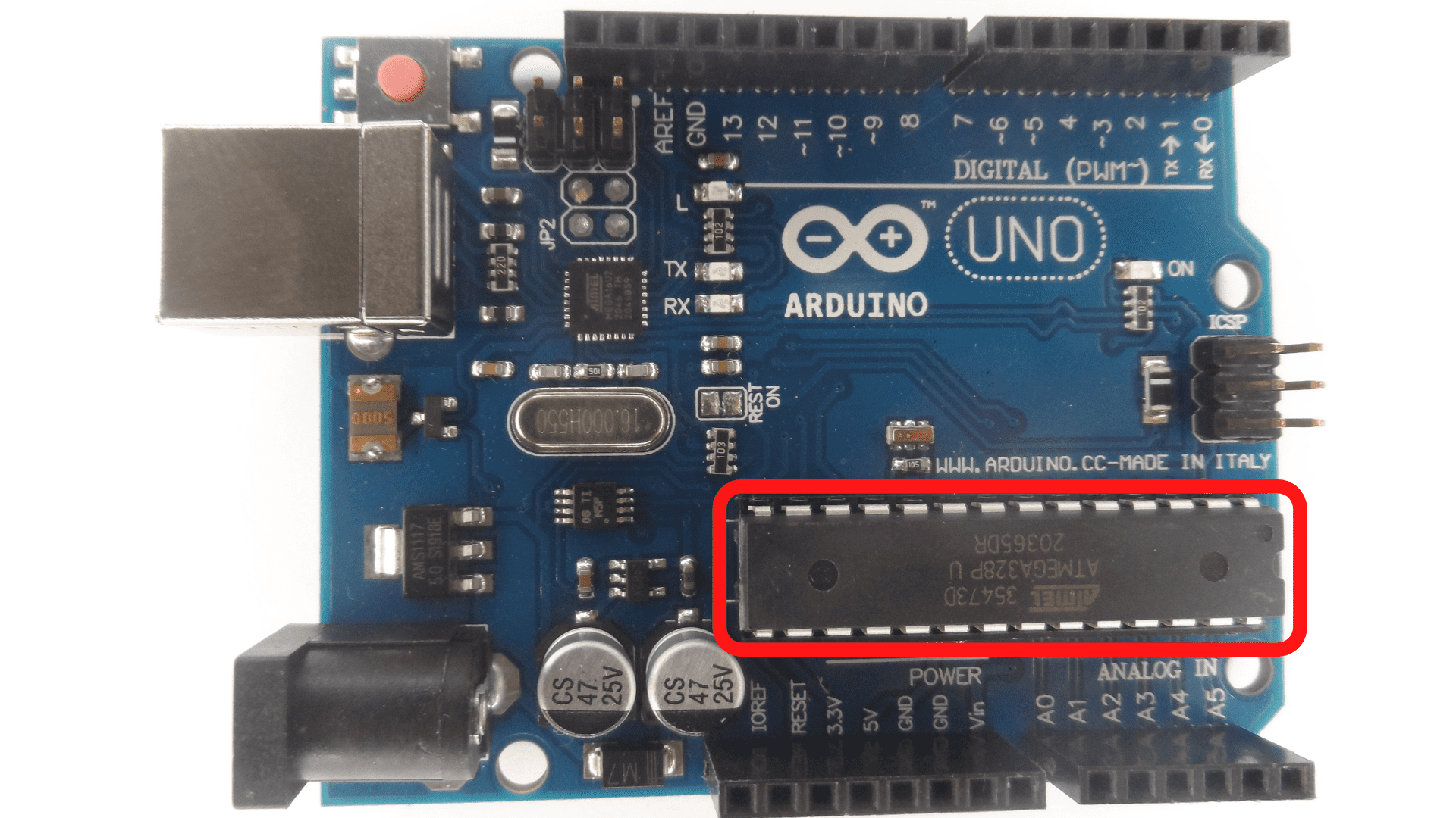
 8- ATmega Microcontrollers
AT mega Microcontrollers are a type of mini controller that is used in Arduino boards. It represents the brain and where the programs are stored.
 9- Power LED Indicator The power LED indicator indicates whether power is going to a device or not.
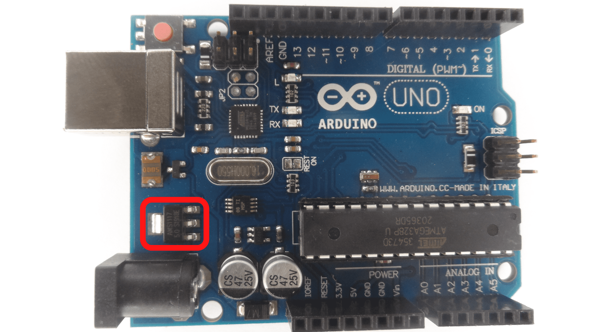
10- Voltage Regulator The voltage regulator regulates the amount of voltage that arrives in the Arduino.
 11- DC Power Barrel Jack The power supply powers the components of the Arduino.
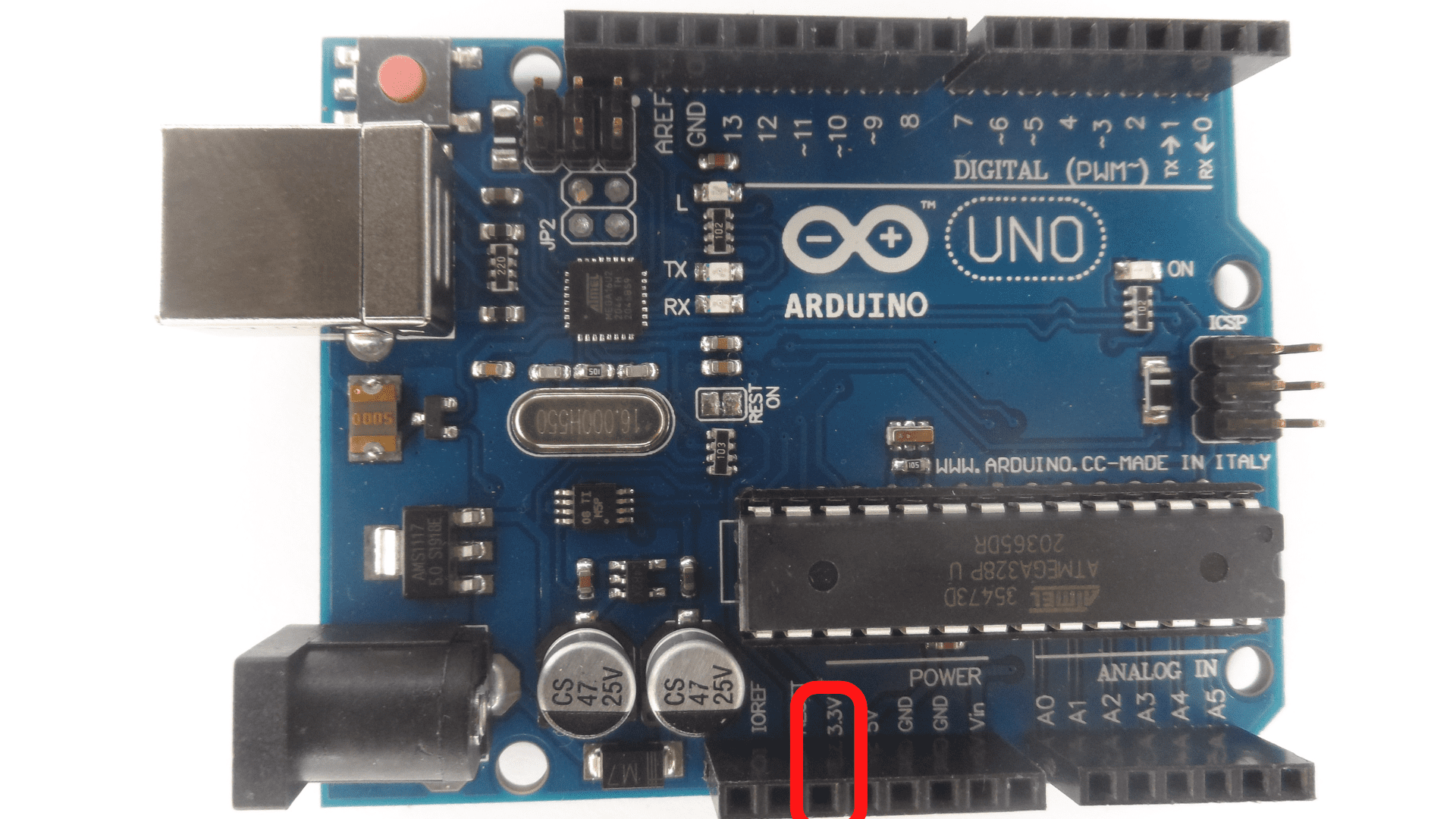
 12- 3.3 PinThe function of this pin is to supply the project with 3.3 volts.
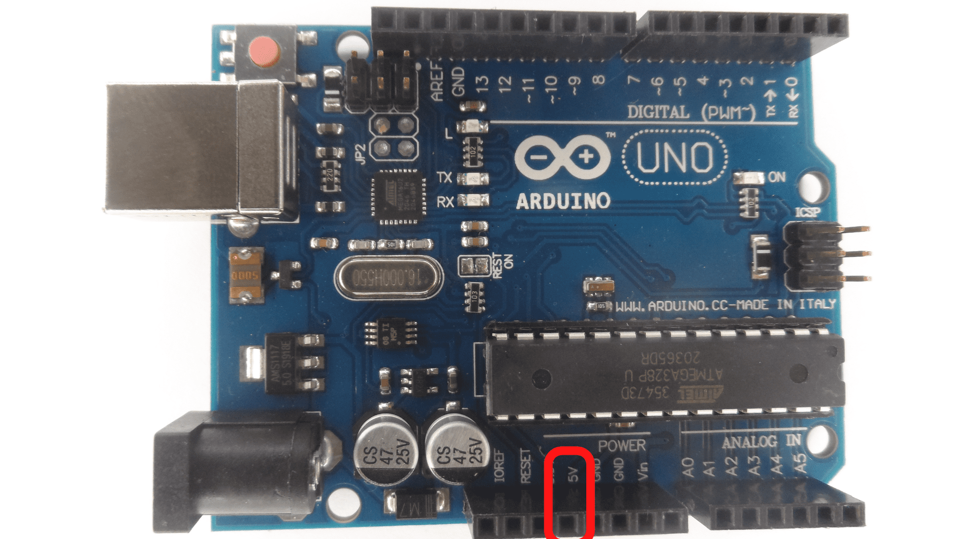
 13- 5 Pin The function of this pin is to supply the project with 5 volts.
 14- Ground PinsThe pins on an Arduino are typically referred to as “ground” pins because they provide the ground reference for the circuit in order to keep the voltage at a safe level.
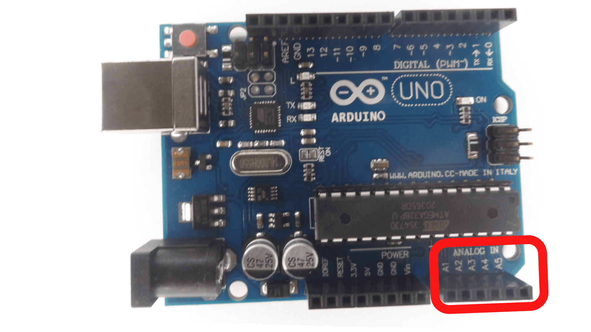
 16 Analog PinsThe Analog pins have the analog signal and convert it to digital.
What do you need for this project?
-Arduino Uno-USB cable to supply power to the Arduino and connect to the laptop. The USB cable will send data back and forth to the laptop. The connection with the USB cable allows the user to program the Arduino.
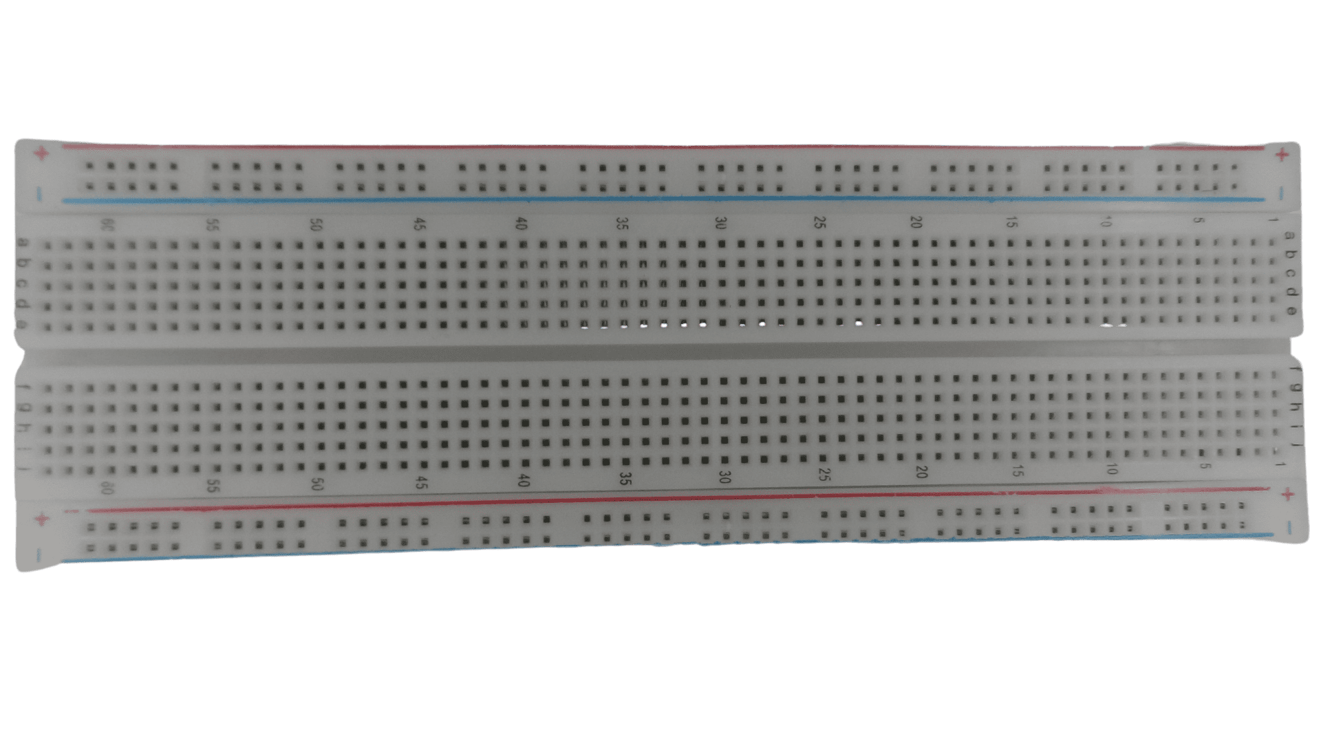
-Solderless breadboard allows the user to insert components together.
 -Resistor
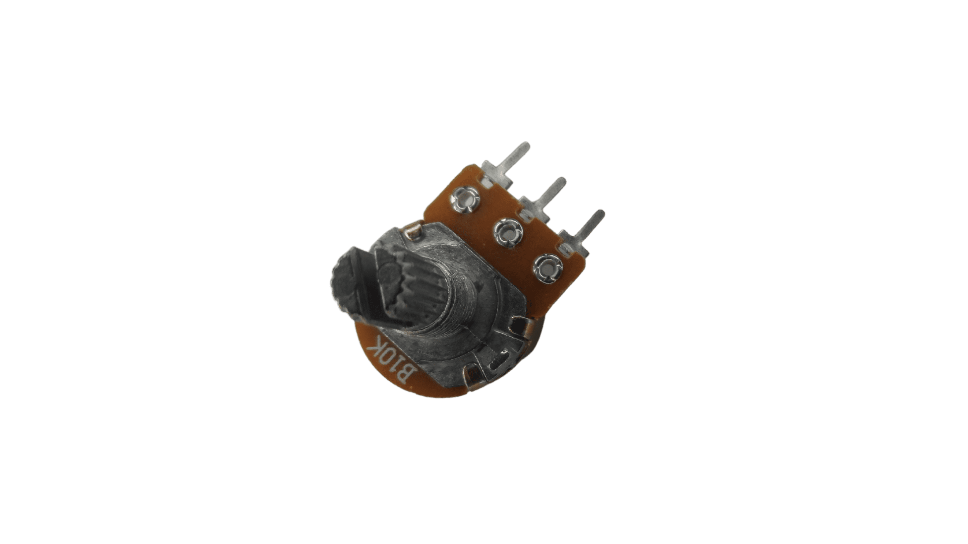
 -potentiometer
-LED or light-emitting diode
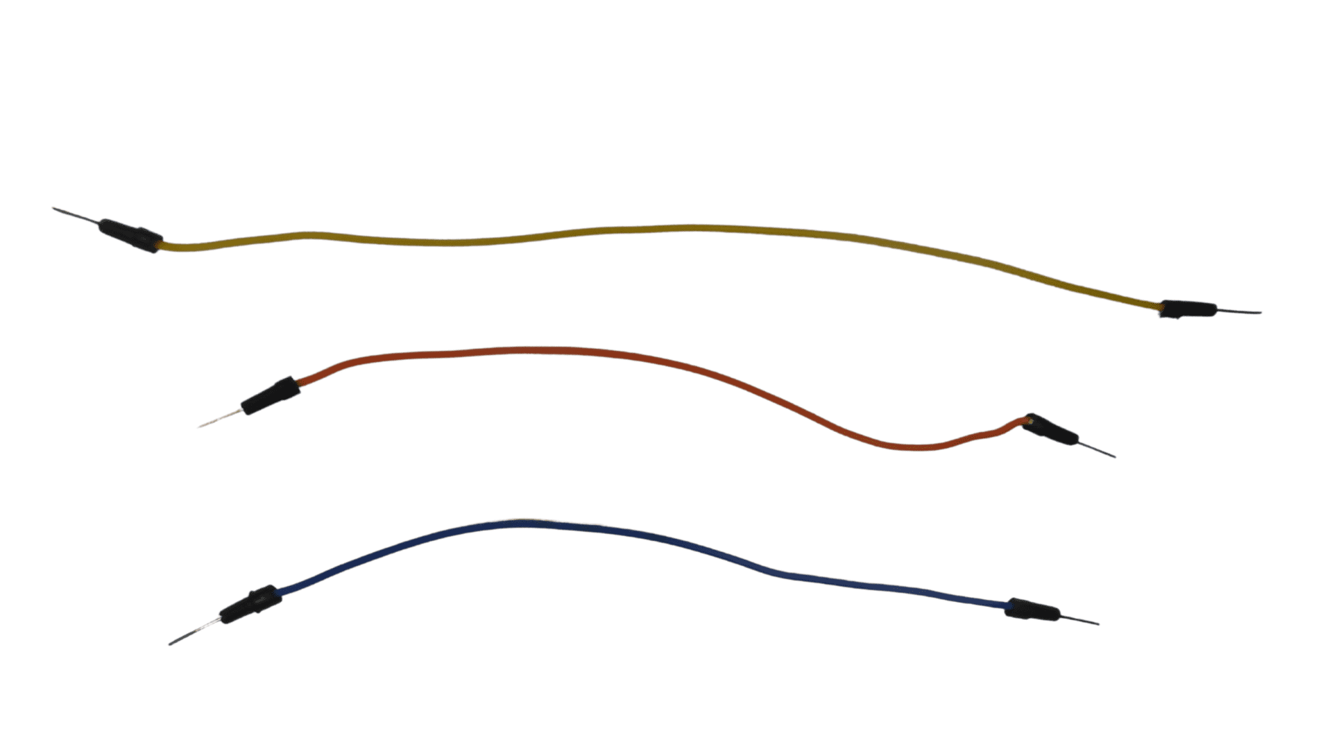
 -Jumper wires: Jumper wires are used to connect the components and attach the components to the Arduino.
 -Laptop

The theoretical side: Learn about the various tools used in the project
The Complete Guide to Breadboards & How They are Changing the Future of Electronics Prototyping
What is a Breadboard?
A breadboard is a device that lets you build an electronic circuit without soldering. Breadboards are boards with rows of holes that are connected by strips of metal.
These metal strips are called “bus bars,” and they allow electrical current to flow from one hole to another.
How to Build Your First Circuit on a Breadboard
This article will teach you how to build your first circuit on a breadboard. You will learn how to use the breadboard, the different parts of a circuit, and how to create an LED light.
The breadboard is a type of prototyping board that allows you to connect components without having to solder them together easily.
The breadboard has many rows and columns of holes that can be used for inserting wires or other components.
The columns are typically labeled with letters (A-H), while the rows are labeled with numbers (1-30).Each hole in the board has two metal pads underneath it, which serve as connection points for electricity.
How to Use a Breadboard for Microcontroller Projects
A breadboard is a type of electrical circuit board that can be used to make temporary circuits or even permanent ones. It consists of a pattern of holes (sometimes in rows, sometimes in columns) into which short lengths of wire called “jumper wires” can be inserted.
Breadboards are great for prototyping circuits because they allow the user to quickly make changes and troubleshoot their circuit without having to create an entirely new one each time.
Breadboards are also good for projects that require many different components because they allow you to plug them all together without needing a lot of space.
Are Breadboards the Best Choice for Prototyping Electronics?
The breadboard is a type of circuit board that is used to design and test electronic circuits. It is also known as a prototyping board or a solderless breadboard.
Breadboards are great for prototyping circuits because they allow you to quickly and easily connect components without having to solder them together.
However, they are not the most suitable choice for making permanent circuits or when you need to make more advanced electronics like microcontrollers.
Complete Guide to Resistor Types, Values, and Applications
What is a Resistor?
 A resistor is a passive two-terminal electrical component that implements electrical resistance as a circuit element. The current flowing through the device is proportional to the voltage applied across its terminals.
The primary function of the resistor is to reduce current flow and limit voltage by providing opposition to electric current.
Resistors are used in electronic circuits to protect sensitive components from high currents and in power distribution systems to limit the peak voltage that reaches customers.
Resistors are usually made from thin wire wound into coils, with an insulating layer on top, but they can also be constructed using thick wires or foil sheets inserted between metal plates.
Electrical Resistance Basics information
Electrical resistance is the opposition that a material offers to the flow of electric current. It is measured in ohms (Ω). The higher the resistance, the more difficult it is for an electric current to flow through a material.
The basic unit of electrical resistance is called the ohm. The symbol for an ohm is Ω, and it’s represented by an omega symbol with a subscript “r” inside it.
The Different Types of Resistors
There are four types of resistors:
1) Carbon Film Resistors: These are the most common resistors. They have lower resistance and are cheaper than other types, but they also have a higher tolerance.2) Metal Film Resistors: These resistors are more accurate and stable than carbon film resistors, but they cost more.3) Thick Film Resistors: These are the most precise type of resistor, but they also cost more.4) Thin Film Resistors: They are the least expensive type of resistor. However, their accuracy is low, and their tolerance is high.
Resistor Values & Uses Application
A resistor is an electrical component that resists the flow of electric current. Resistors are used to protect circuits from voltage spikes and surges, reduce signal noise, and stabilize voltage levels. They are also used to reduce the power consumption of motors.
This section will explore different resistors and their uses in various applications.The first type of resistor is called a fixed resistor or a constant resistance. Fixed resistors have a set resistance value and do not change regardless of the amount of current flowing through them.
The second type is called a variable resistor or potentiometer. A variable resistor has two terminals with one end connected to the ground while the other can be adjusted with a knob or screwdriver (potentiometer). Variable resistors can be used as volume controls for radios.
Everything You Need to Know About Potentiometers
Introduction and What is a Potentiometer?
A potentiometer is a variable resistor circuit used to control the electric current or voltage intensity.
The potentiometer is one of the essential components in electronics and can be used for various purposes. For example, it can adjust an audio signal or change the volume on a TV set.
It can also be used in things like your car’s dashboard, where you would use it to adjust the temperature on your air conditioning unit.
How to Determine the Type of Potentiometers and How to Wire Them Up Correctly
The type of potentiometers and how to wire them up correctly will vary depending on the type of circuit you are building.
For example, if you are building a voltage divider circuit, you would want to use a potentiometer in series with the upper resistor, in parallel with the lower resistor.
Potentiometers and Temperature Sensitivity
This section will explore how potentiometers work and what they are used for.A potentiometer is a resistor with three terminals.
It can be used to measure and control voltage, current, or resistance by turning a knob.
Potentiometers are most commonly used in projects that involve measuring or controlling voltage, current, or resistance by turning a knob.
Potentiometers are most commonly used in projects that involve measuring or controlling voltage, current, or resistance by turning a knob.
What is LED Lighting? Why is it so Popular?
LED lighting is solid-state lighting that uses light-emitting diodes (LEDs) as the light source. LEDs are semiconductor devices that emit incoherent narrow-spectrum light when forward biased with a voltage.
Furthermore, they are the most efficient form of solid-state lighting and the most environmentally friendly type, leading to increased luminance and reduced power consumption in different contexts. For this project, the use of the LED will be an indicator.
The LED has two legs, one longer than the other. The longer is positive, and the shorter is negative. It would be best to be careful about how you insert this into it.
Different Types of Arduino Jumper Wires
Different types of jumper wires are made for different purposes. The following is a list of the most common types of jumper wires and their use cases:
1. Male-to-male: These are used to connect two female pins; these are typically used in breadboards and other prototyping projects.
2. Female-to-female: These are used to connect two female pins; they can be used when you want to connect an Arduino or another type of microcontroller to another piece of hardware with female pins on it like sensors or sensors LED lights.
3. Male-to-female: This is the opposite of a male-to-male jumper wire; this is used to connect one male pin with another male pin; for example, if you want to use a servo motor with your Arduino board, you need some jumper wires.
Installing and connecting the Arduino
Installation of Arduino to a laptop is not as complicated as it may seem. This article will guide you through the process step by step.
First, you need to download Arduino Software from the official website. You can find the download link on the front page of the website. Once downloaded, open it and pursue the instructions on your screen. Connect the laptop to the Arduino using the USB cable.
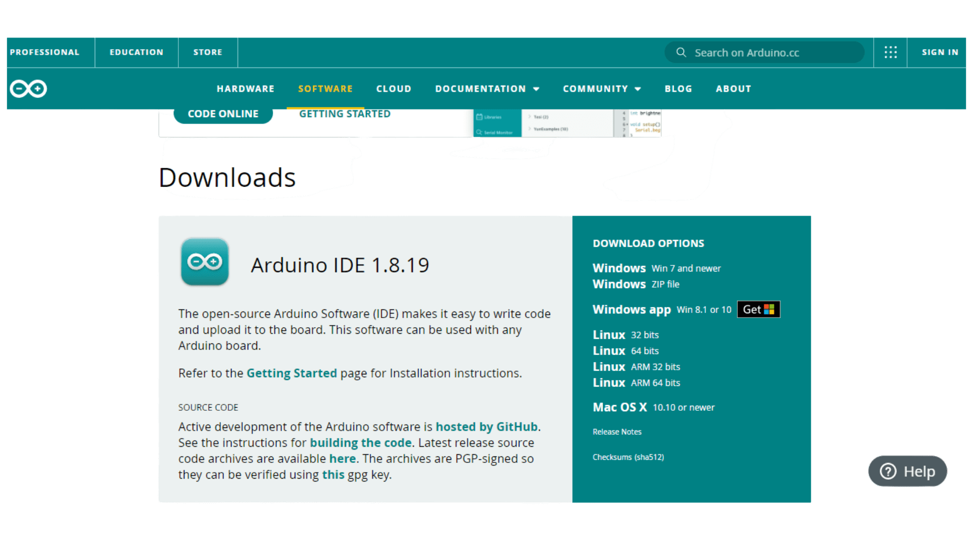 After installation, plug in your board and wait for drivers to install themselves automatically. Once done, open Arduino IDE and select Tools>Board>Arduino/Genuino Unoand then Tools>Port>COMxx (where xx is your COM port).
 Choose your port connection!

Blink sketch project
Blink sketch project: This project lets you practice the simplest exercise you can do with an Arduino to remarque physical output: blinking the onboard LED.
Once done with these steps, you should be able to upload a sketch onto your board
Open the Arduino application then choose from the menu:
File——–>Examples——–>01 Basics—>Blink
 Do not bother with the content of the code shown on the screen. It is a previously prepared code that is ready to run automatically and can be easily modified.
Currently the code is on the Arduino program and not on the Arduino itself. To download the code on the Arduino, click on the arrow button in the accompanying image.
 Wait for the download, and the code will run automatically after downloading it to the Arduino. The exercise is part one of your starter kit project for beginners.
 The sketch is loaded up already. The blink rate is shown on Arduino Uno.
Change the delay value and notice the blink rate
// the setup function runs once when you press reset or power the boardvoid setup() {// initialize digital pin LED_BUILTIN as an output.pinMode(LED_BUILTIN, OUTPUT);}// the loop function runs over and over again forevervoid loop() {digitalWrite(LED_BUILTIN, HIGH); // turn the LED on (HIGH is the voltage level)delay(1000); // wait for a seconddigitalWrite(LED_BUILTIN, LOW); // turn the LED off by making the voltage LOWdelay(1000); // wait for a second}
We can develop the project and make the blink rate emitted by a LED outside the Arduino. The exercise is part two of your starter kit project for beginners.
We need a 220 ohm resistor because the output voltage of the Arduino is enough that it will eventually burn out the LED.
So we are adding this resistor to restrict the flow of electricity through it means that there is not too much electricity going through it.

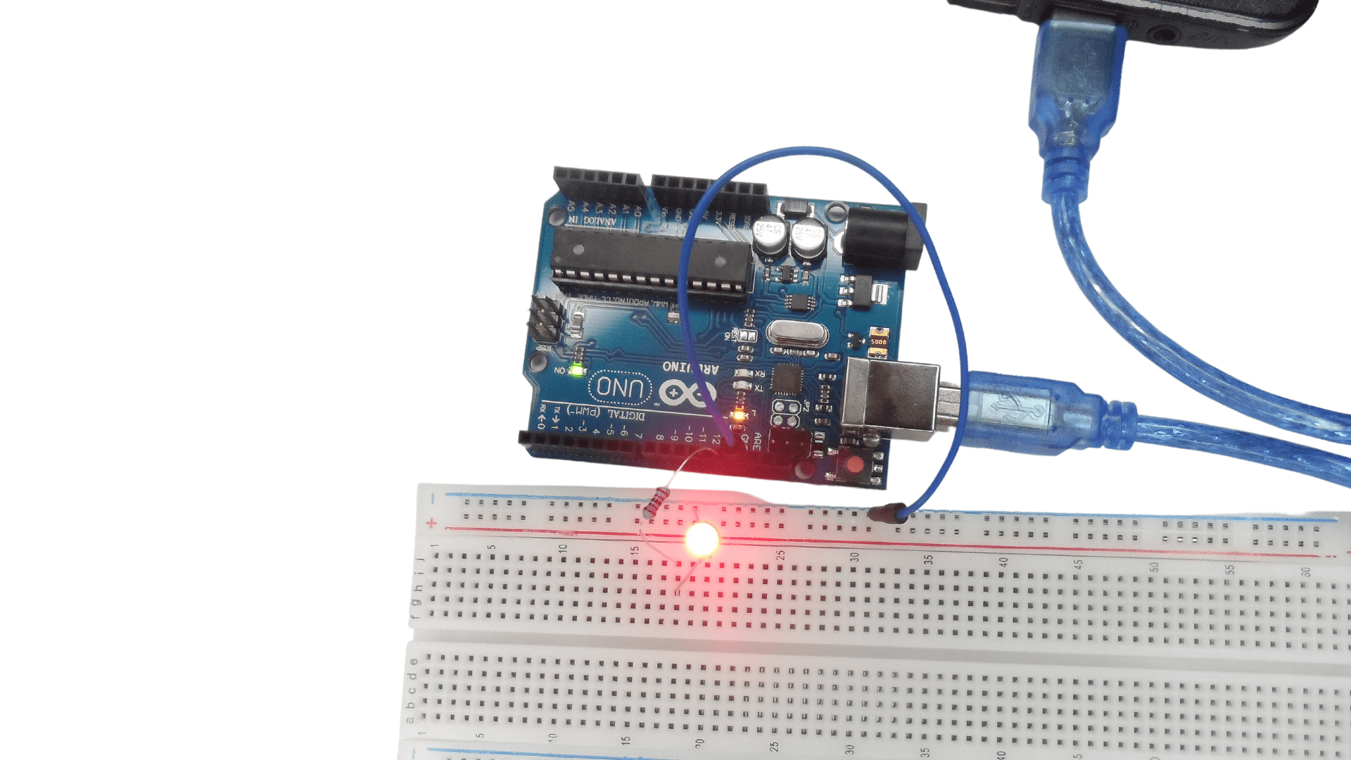
- Connect the ground wire between the Arduino. Use anyone from the ground. Link the GND of the Arduino to the blue rail of the solderless breadboard. Now the entire blue rail on the side is ground; This blue side rail is electrically ground, and anything you plug along that rail will be electrically ground.
- Add the 220-ohm resistor to the solderless breadboard on digital PIN 13 of the Arduino Uno and the other end of the resistor into J18 of the solderless bread.
- Put the short lead of the LED anywhere alone the negative rail put positive lead in the identical row that the resistor went into; put into H18, for example.
- Be careful that the two leads of the LED do not touch each other to avoid shortening the circuit. So the LED is blinking at the same rate that the little that little LED of the Arduino. They are both parts of PIN 13 of the Arduino Uno.
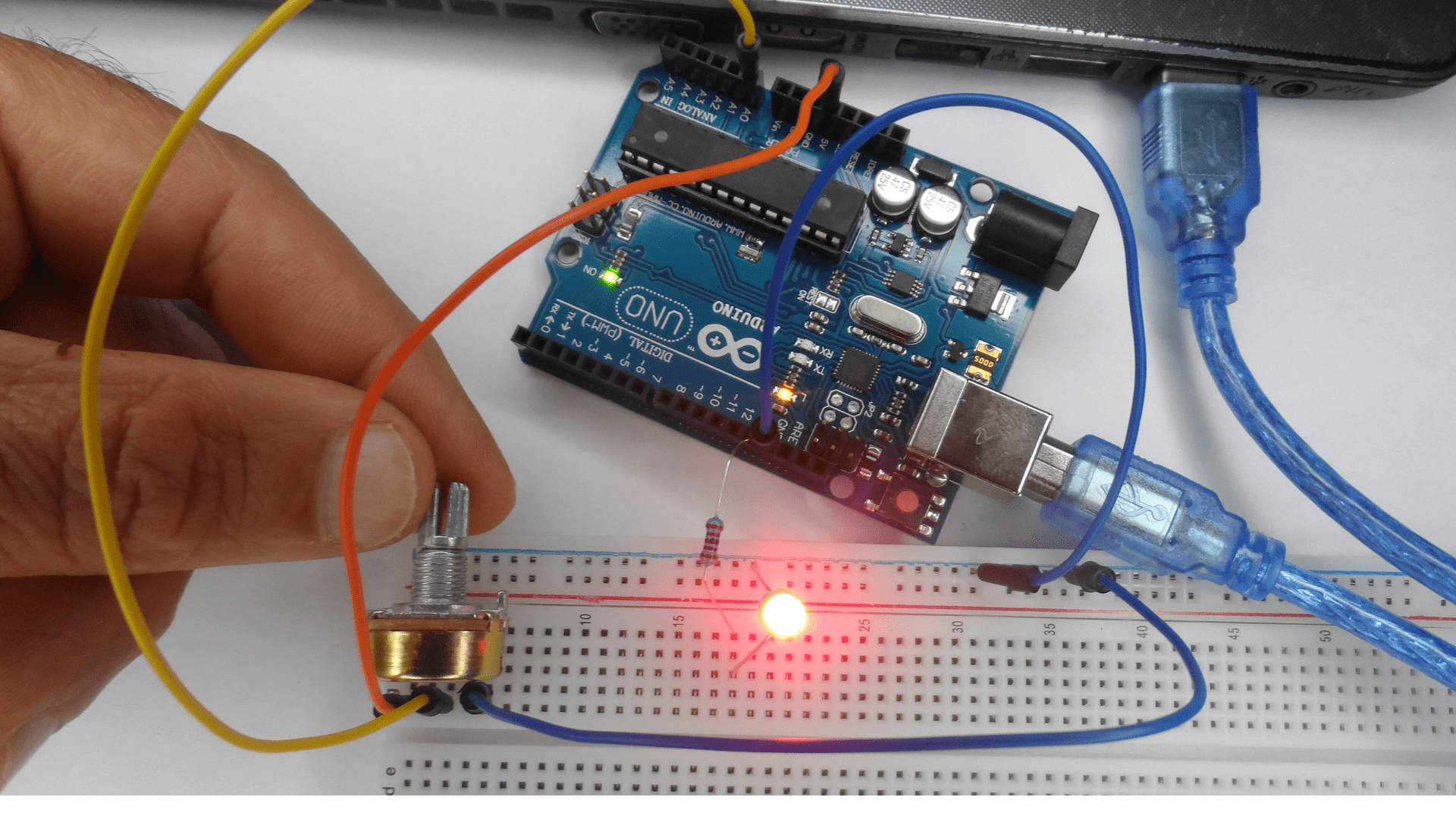
 We can develop this project and put a mechanism to control the LED’s blink using the potentiometer. Remember that the potentiometer is a variable resistor.
 voltage intensity
- Ad the potentiometer in pins one, three, and five in column Jof the solderless breadboard.
- Attach the jumper wire from row five to the rail ground to give a ground connection to the potentiometer.
- Attach a red jumper wire from row one to the plus five volts pin over to pin five volts of the Arduino
- Attach a yellow jumper wire from row three over analog pin zero
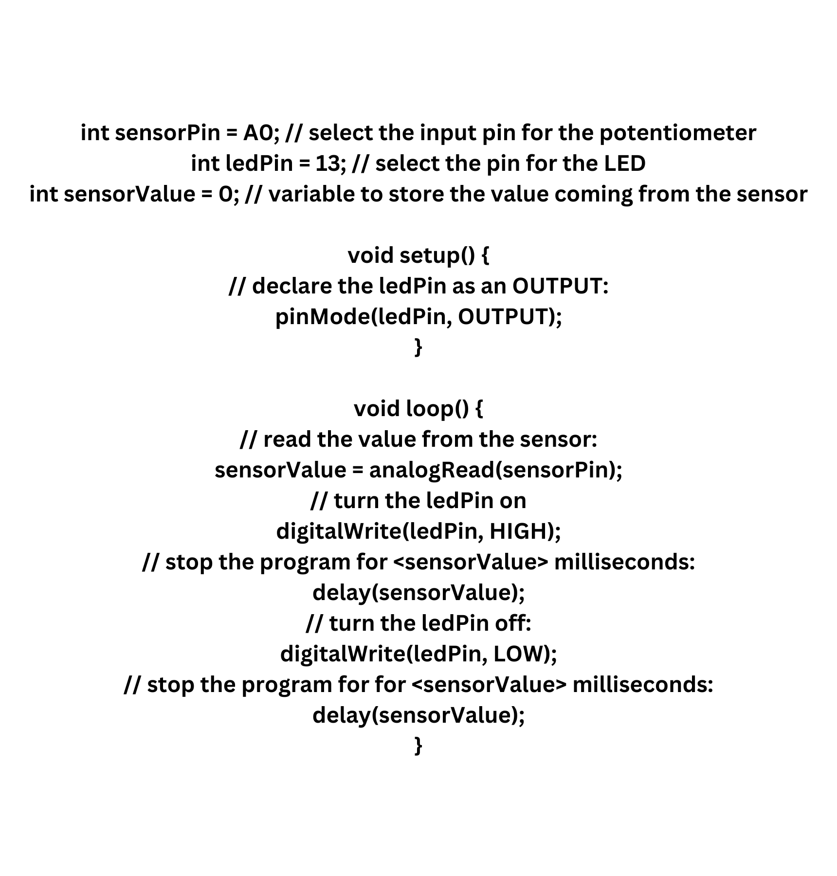
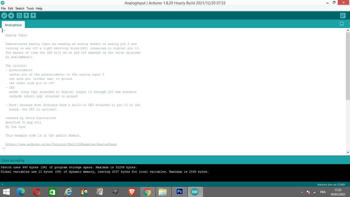
- Everything is connected. Load up the analog input sketch from the Arduino application. See as shown in the attached image.

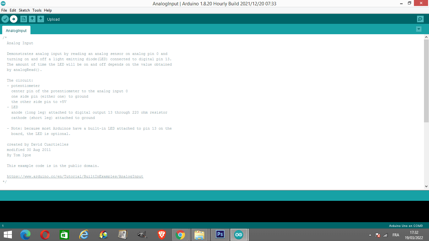
 Turn the knob of the potentiometer to the right or the left; then, you can see the change of the rate of the LED light.
 Take a look at the code
The code of analog input sketch
