Table of Contents

Introduction

In the field of DIY electronics as well as hobbyist projects making a reliable and solid clock is an increasingly sought-after project. The ability to combine the flexibility of the Arduino and the precision of GPS technology can take this project to a new level. Utilizing the power of GPS technology and an Arduino sketch with seven segments clock with GPS users can create the perfect time-keeping gadget that displays not just the exact time, but with precision and accuracy, but also provides synchronization to global atomic clocks.

This article explains the process step-by-step of creating an Arduino sketch that has seven segments clock GPS project. Beginning with understanding the essential components to posting and writing your code, we’ll help users through the process of creating a functioning and precise clock.

No matter if you’re an experienced Arduino creator or just a newbie looking to learn more the possibilities, this tutorial will give you the skills to create your own timepiece.
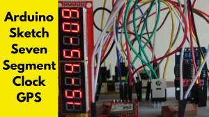
Arduino Sketch Seven Segment Clock GPS

Understanding the Components

Before you begin the design of your Arduino sketch seven segment clock GPS It is essential to know the most important components that are required to complete the project.

1. Arduino Board

The central component of your clock, called the Arduino board (such as the Arduino Uno) acts as the microcontroller, which receives signals from your GPS module, and also controls the seven-segment display.

2. Seven Segment Display

A seven-segment display is an electronic display device that is used for displaying decimal numbers. This project will use the display will have four digits. will show the present time.

3. GPS Module

The GPS module is able to receive signals from satellites, which determine precisely where and when it is. In this case, devices such as NEO-6M are commonly used. NEO-6M are frequently employed because of their dependability and easy integration.

4. Real-Time Clock (RTC) Module (Optional)

Although the GPS module is accurate in its time, adding the RTC component (like the DS1307, or DS3231) will ensure that the clock is operational even during times when GPS signals aren’t available.

5. Resistors and Transistors

Resistors limit the current to the seven segment display, and transistors act as switches to control the display segments efficiently.

6. Breadboard and Jumper Wires

These are essential for prototyping the circuit without soldering, allowing for easy adjustments and testing.

7. Power Supply

A stable power source, such as a 5V adapter or USB connection, ensures consistent operation of the clock.

Setting Up the Hardware

With the components in hand, the next step is assembling the hardware for your arduino sketch seven segment clock gps.

1. Connecting the Seven Segment Display

  • Cathode and. Anode Display Find out if your seven-part display is common cathode or common since this determines the way you join the segments.
  • wirg insegments: Each segment (A-G) from the display the digital pins of the Arduino using present-limiting resistors (typically 220 ohms). If you are using a display with four digits there is a possibility that you will need to add more pins or shift registers to control the segments effectively.
  • Digit Control The common pins of each digit with separate digital pins which allows the Arduino to decide which digit is active the moment.

2. Integrating the GPS Module

  • Power Connections Make sure you connect the VCC as well as the GND pins of the GPS module to Arduino’s 5V and GND pins, respectively.
  • Data Communications: Make use of your RX as well as TX pins for serial communications. It is recommended to use the software serial (e.g. pins 3 and 4) to ensure that there are no conflict with Arduino’s main serial interface.

3. Adding the RTC Module (Optional)

  • I2C Connection In the case of the RTC module, you must connect the SCL and SDA pins to the Arduino’s A4 or A5 pins.
  • Power Source: Make sure your RTC module’s power supply is activated by the GND and 5V pins.

4. Finalizing the Circuit

  • Transistor Setup Utilize transistors to change the numbers of the display with seven segments and ensure that the Arduino is able to handle the current with no harm.
  • Common Ground Make sure that all circuit components have a common ground in order in order to ensure that voltage levels are consistent throughout the circuit.

5. Testing the Hardware

Before you move on to the programming stage, turn on your device to confirm that your connections are secure and that the 7 segment display functions properly. Each segment should be lit according to the instructions when controlled with the Arduino.

Writing the Arduino Sketch

The Arduino sketch is the heart of your Arduino sketch’s seven segment clock GPS and determining how hardware components communicate to display precise time.

1. Setting Up the Environment

  • Arduino IDE: Make sure you are running the most recent version of the Arduino Integrated Development Environment (IDE) installed on your PC.
  • Libraries installation: Installation of the required libraries including SoftwareSerial to support GPS communications and Adafruit_GPS to process GPS data. If you are using the RTC module, install the necessary libraries similar to the RTClib library.
  • 2. Initializing Variables and Libraries

Create your sketch by adding all necessary libraries, and then defining pin connections to the display with seven segments and the GPS module.

The code

#include <SoftwareSerial.h>
#include <Adafruit_GPS.h>
#include <Wire.h>
#include <RTClib.h>

// Define GPS module connections
SoftwareSerial mySerial(4, 3); // RX, TX
Adafruit_GPS GPS(&mySerial);

// Define RTC
RTC_DS3231 rtc;

// Define seven segment display pins
const int segmentA = 2;
const int segmentB = 5;
const int segmentC = 6;
const int segmentD = 7;
const int segmentE = 8;
const int segmentF = 9;
const int segmentG = 10;
const int digit1 = 11;
const int digit2 = 12;
const int digit3 = A0;
const int digit4 = A1;

3. Setting Up the GPS Module

Configure the GPS module to output the necessary data for time synchronization.

The code

void setup() {
// Initialize serial communication
Serial.begin(9600);
mySerial.begin(9600);

// Initialize GPS
GPS.begin(9600);
GPS.sendCommand(PMTK_SET_NMEA_OUTPUT_RMCGGA);
GPS.sendCommand(PMTK_SET_NMEA_UPDATE_1HZ);

// Initialize RTC
if (!rtc.begin()) {
Serial.println(“Couldn’t find RTC”);
while (1);
}

// Initialize display pins
pinMode(segmentA, OUTPUT);
pinMode(segmentB, OUTPUT);
pinMode(segmentC, OUTPUT);
pinMode(segmentD, OUTPUT);
pinMode(segmentE, OUTPUT);
pinMode(segmentF, OUTPUT);
pinMode(segmentG, OUTPUT);
pinMode(digit1, OUTPUT);
pinMode(digit2, OUTPUT);
pinMode(digit3, OUTPUT);
pinMode(digit4, OUTPUT);

// Turn off all digits initially
digitalWrite(digit1, HIGH);
digitalWrite(digit2, HIGH);
digitalWrite(digit3, HIGH);
digitalWrite(digit4, HIGH);
}

4. Parsing GPS Data

Create functions to parse GPS data and update the RTC module accordingly.

The code

void loop() {
// Read GPS data
char c = GPS.read();

if (GPS.newNMEAreceived()) {
if (!GPS.parse(GPS.lastNMEA())) {
return;
}
if (GPS.fix) {
// Update RTC with GPS time
DateTime now = rtc.now();
rtc.adjust(DateTime(GPS.year, GPS.month, GPS.day, GPS.hour, GPS.minute, GPS.seconds));
}
}

// Display time on seven segment
DateTime now = rtc.now();
displayTime(now.hour(), now.minute(), now.second());
}

5. Displaying Time on the Seven Segment Display

Use the feature to regulate the seven-segment display in accordance with the current time.

The code

void displayTime(int hour, int minute, int second) {
// Format time as HH:MM
int digits[] = {hour / 10, hour % 10, minute / 10, minute % 10};

for (int i = 0; i < 4; i++) {
// Turn off all digits
digitalWrite(digit1, HIGH);
digitalWrite(digit2, HIGH);
digitalWrite(digit3, HIGH);
digitalWrite(digit4, HIGH);

// Set segments for current digit
displayDigit(digits[i]);

// Turn on the current digit
switch(i) {
case 0:
digitalWrite(digit1, LOW);
break;
case 1:
digitalWrite(digit2, LOW);
break;
case 2:
digitalWrite(digit3, LOW);
break;
case 3:
digitalWrite(digit4, LOW);
break;
}

delay(5); // Adjust for flicker rate
}
}

void displayDigit(int num) {
// Define segment patterns for digits 0-9
const byte numToSegments[10] = {
0b00111111, // 0
0b00000110, // 1
0b01011011, // 2
0b01001111, // 3
0b01100110, // 4
0b01101101, // 5
0b01111101, // 6
0b00000111, // 7
0b01111111, // 8
0b01101111 // 9
};

byte segments = numToSegments[num];

digitalWrite(segmentA, segments & 0b00000001);
digitalWrite(segmentB, segments & 0b00000010);
digitalWrite(segmentC, segments & 0b00000100);
digitalWrite(segmentD, segments & 0b00001000);
digitalWrite(segmentE, segments & 0b00010000);
digitalWrite(segmentF, segments & 0b00100000);
digitalWrite(segmentG, segments & 0b01000000);
}

6. Uploading the Sketch

Connect the Arduino to your computer using USB and then upload your sketch with the Arduino IDE. Examine the output from the serial connection to verify you are sure that your GPS module has received the data as well as to ensure that the RTC is working correctly.

Integrating the GPS Module

The GPS module is pivotal in providing accurate time data to your arduino sketch seven segment clock gps. Here’s how to ensure seamless integration:

1. GPS Signal Reception

Put your GPS device on a flat surface or next to a window, in order so that it receives signals from many satellites. Clear views of the sky improves signals’ strength and accuracy.

2. Parsing GPS Data

Use using the GPS Adafruit library to decode the inbound NMEA messages that come from GPS module. GPS module. The data contains the date, time and information about the location.

The code

if (GPS.newNMEAreceived()) {
if (!GPS.parse(GPS.lastNMEA())) {
return;
}
if (GPS.fix) {
// Update RTC with GPS time
rtc.adjust(DateTime(GPS.year, GPS.month, GPS.day, GPS.hour, GPS.minute, GPS.seconds));
}
}

3. Handling GPS Lock

Make sure that the code is checking to see if there is an active GPS fix prior to resetting the RTC. It prevents incorrect time information not being displayed when there is a weak GPS signal is not strong or available.

The code

if (GPS.fix) {
// Update RTC with GPS time
}

4. Redundancy with RTC Module

Integrating the RTC module can provide an automatic fallback feature, which allows your clock to keep the exact time even if GPS signals go out for a short period of time.

Displaying Time on the Seven Segment Display

The main function of the Arduino sketch 7 segment clock GPS is in the precise display of the time in real-time. This is how you can achieve it:

1. Multiplexing the Display

For controlling multiple digits on the limited Arduino pins, you can implement multi-channeling. This is a method of rapidly changing between the digits and creating the appearance that all of the of the digits are on at once.

The code

for (int i = 0; i < 4; i++) {
// Turn off all digits
digitalWrite(digit1, HIGH);
digitalWrite(digit2, HIGH);
digitalWrite(digit3, HIGH);
digitalWrite(digit4, HIGH);

// Set segments for current digit
displayDigit(digits[i]);

// Turn on the current digit
switch(i) {
case 0:
digitalWrite(digit1, LOW);
break;
case 1:
digitalWrite(digit2, LOW);
break;
case 2:
digitalWrite(digit3, LOW);
break;
case 3:
digitalWrite(digit4, LOW);
break;
}

delay(5); // Adjust for flicker rate
}

2. Segment Control

Create patterns for each digit (0-9) and manage each segment according to. It ensures that correct numbers are shown based on the time of day.

The code

void displayDigit(int num) {
// Define segment patterns for digits 0-9
const byte numToSegments[10] = {
0b00111111, // 0
0b00000110, // 1
0b01011011, // 2
0b01001111, // 3
0b01100110, // 4
0b01101101, // 5
0b01111101, // 6
0b00000111, // 7
0b01111111, // 8
0b01101111 // 9
};

byte segments = numToSegments[num];

digitalWrite(segmentA, segments & 0b00000001);
digitalWrite(segmentB, segments & 0b00000010);
digitalWrite(segmentC, segments & 0b00000100);
digitalWrite(segmentD, segments & 0b00001000);
digitalWrite(segmentE, segments & 0b00010000);
digitalWrite(segmentF, segments & 0b00100000);
digitalWrite(segmentG, segments & 0b01000000);
}

3. Time Formatting

Create a format for the time data retrieved by your RTC or GPS module in a way that is that is suitable to be displayed. This typically involves breaking down the hours and minutes into separate numerals.

The code

DateTime now = rtc.now();
int digits[] = {now.hour() / 10, now.hour() % 10, now.minute() / 10, now.minute() % 10};

Troubleshooting Common Issues

If you’re careful there are bound to be issues in the process of making your arduino sketch 7 segment clock GPS. These are the common challenges as well as solutions to them:

1. Display Flickering

The reason: Inadequate multiplexing speed or lack of a current supply.

Answer: Adjust the delay between the digit switches. By reducing the delay, you can reduce flicker. Also, make sure that the transistors are switching correctly digits with no delay.

2. GPS Signal Not Acquired

The reason: Poor antenna placement or obstructions that block satellite signals.

solution: Relocate the GPS module to an open region with a clear view of the night sky. Make sure your antenna’s attached and is not damaged.

3. Inaccurate Time Display

Reason: RTC module not synced with GPS information or has a problem with the connection.

Solutions: Check RTC connections and verify that the module has been properly initialized in the sketch. Verify you are sure that your GPS module provides precise time information and it is correctly updating the RTC.

4. Non-Responsive Segments

The reason: Incorrect wiring or damaged display segments.

Solutions: Double-check all connections between the Arduino and the seven-segment display. Examine each segment separately to determine if there are any malfunctioning components.

5. Software Serial Conflicts

The reason: Overlapping use of serial pins to enable GPS communication as well as debugging.

Solution Utilize separate pins to communicate with software serially using the GPS module in order to avoid conflict with Arduino’s main serial interface that is used to debug.

Making Your Clock More Effective with Other Features

After you have your Arduino sketch seven-segment clock GPS is working, you can think of including features that will enhance the functionality and ease of use.

1. Brightness Control

Install the PWM (Pulse Width Modulation) to adjust the illumination of the seven segment display. It allows you to adjust the lighting that is based on the conditions of the surrounding.

The code

const int brightnessPin = A2;

void setup() {
pinMode(brightnessPin, OUTPUT);
// Other setup code
}

void setBrightness(int level) {
analogWrite(brightnessPin, level);
}

2. Alarm Functionality

Include an alarm function that activates a buzzer LED at a specific time that provides audible or visible alarms.

The code

const int buzzer = A3;
DateTime alarmTime;

void checkAlarm(DateTime now) {
if (now.hour() == alarmTime.hour() && now.minute() == alarmTime.minute()) {
digitalWrite(buzzer, HIGH);
} else {
digitalWrite(buzzer, LOW);
}
}

3. Timezone Adjustment

Users can set their own timezones and adjust the UTC offset in accordance with their location.

The code

const int timezoneOffset = -5; // Example for EST

void displayTime(int hour, int minute) {
hour += timezoneOffset;
if (hour < 0) hour += 24;
if (hour >= 24) hour -= 24;
// Continue with display logic
}

4. Displaying Date and Seconds

Extend the display to display the dates and seconds using more digits, or by integrating several display.

 The code
// Example to include seconds
int digits[] = {hour / 10, hour % 10, minute / 10, minute % 10, second / 10, second % 10};

5. Network Time Synchronization

Incorporate Wi-Fi and Ethernet modules for synchronizing times with online-based NTP (Network Time Protocol) servers. This provides the alternative of GPS for accuracy of time.

Frequently Asked Questions

1. What’s the arduino sketch? seven segment clock with GPS?

A arduino sketch with seven segments clock with GPS is a diy project which makes use of an Arduino microcontroller to manage the display in seven segments, that displays the time of the day, which is that is synchronized to an GPS module that provides high precision.

2. What are the benefits of using the GPS module to make an alarm clock?

The GPS module gives accurate time information by capturing signals from atomic clocks located on satellites. This ensures that the clock is highly accurate, even with no any manual adjustments.

3. What can I do to make this project with out an RTC module?

The answer is yes, however, adding an RTC module can provide an alternative source of time that ensures the clock functions in a precise manner regardless of GPS signals are not available.

4. How can I stop flickering from the seven-segment display?

Change the delay of multiplexing in your Arduino sketch. By reducing the delay, you can reduce flickering, while ensuring that transistors are switched on quickly will aid.

5. Which Arduino board is the most suitable to use for this task?

The Arduino Uno is suitable for newbies. However, boards with greater digital I/O ports or integrated serial communications (like Arduino Mega) Arduino Mega) may offer more features.

6. What do I do to make sure that my GPS module is receiving a clear signal?

Set the GPS unit within an area of open space with an unobstructed vision of the sky far from obstacles such as wall or metallic objects that could block the reception of signals.

7. Do I have the option of displaying the time in various formats like 12 hours?

Absolutely. Change this Arduino sketch to display the time in a 12-hour format. This can be done by altering the hour value and adding AM/PM indicator.

8. How can I include an alarm option to the clock?

Incorporate a LED or buzzer and set the Arduino up to start triggering the alarm at a predetermined moment by comparing the present clock time to the alarm’s time in the sketch.

9. What is the required power source in this project?

A reliable source of 5V power for example, an USB connection, or an 5V adapter, will be sufficient for powering the Arduino, GPS module, as well as the seven-segment display.

10. Can you expand the display so that it displays additional information?

You can also make more digits, or other displays to display details like time, date, and even the weather information by integrating sensors or adding additional modules.

Conclusion

Making the Arduino sketch with seven segments clock GPS is an enlightening and rewarding endeavor which combines electronics, programming with real-world use. With the help of GPS technology, and the flexibility of Arduino the user can create the clock that display the current time with precision, but is also in sync with the atomic standard. If you’re looking to improve your technical abilities, creating a distinctive timepiece or the perfect DIY challenge, this tutorial will help you prepare to start your quest. Explore additional options and personalize the design as well as enjoy admiring your hand-crafted clock run at a precise time.


Pin It on Pinterest

Share This