Introduction
The article Arduino Pins The Ultimate Guide explains all the Arduino Uno Pinout: names, functions, and properties of these components.
The Arduino Uno is the microcontroller board used for building electronics projects. It has many built-in features and can be programmed in C++ and the Arduino programming language.The Arduino Uno has 14 digital I/O pins, six analog input pins, five power output pins, etc.
Arduino Uno R3
Arduino is the open-source electronics prototyping platform that people use to create interactive objects or environments. The Arduino Uno R3 is the latest version of the Arduino board.
It has a USB interface that can be used to program the board and can be powered via the USB cable or an external power supply.
The Uno R3 has 14 digital input/output pins (of which six can be used as PWM outputs), six analog inputs, a 16 MHz quartz crystal, a USB connection, a power jack, and ICSP header, and a reset button. The Uno differs from all initial boards in that it does not use the FTDI USB-to-serial driver chip.
Arduino Pins The Ultimate Guide
The Arduino Uno pinout is a comprehensive guide for the most popular Arduino board. It provides an overview of all the pins and their functions to help you understand how to use them in your projects.
Power Supply Pins
There are two ways to provide power to an Arduino board. You can plug your board into the computer’s USB port or use a separate power supply.
If you decide to use a separate power supply, it must be at least 5 volts and have the correct polarity (either center positive or center negative) and a 3.3V.
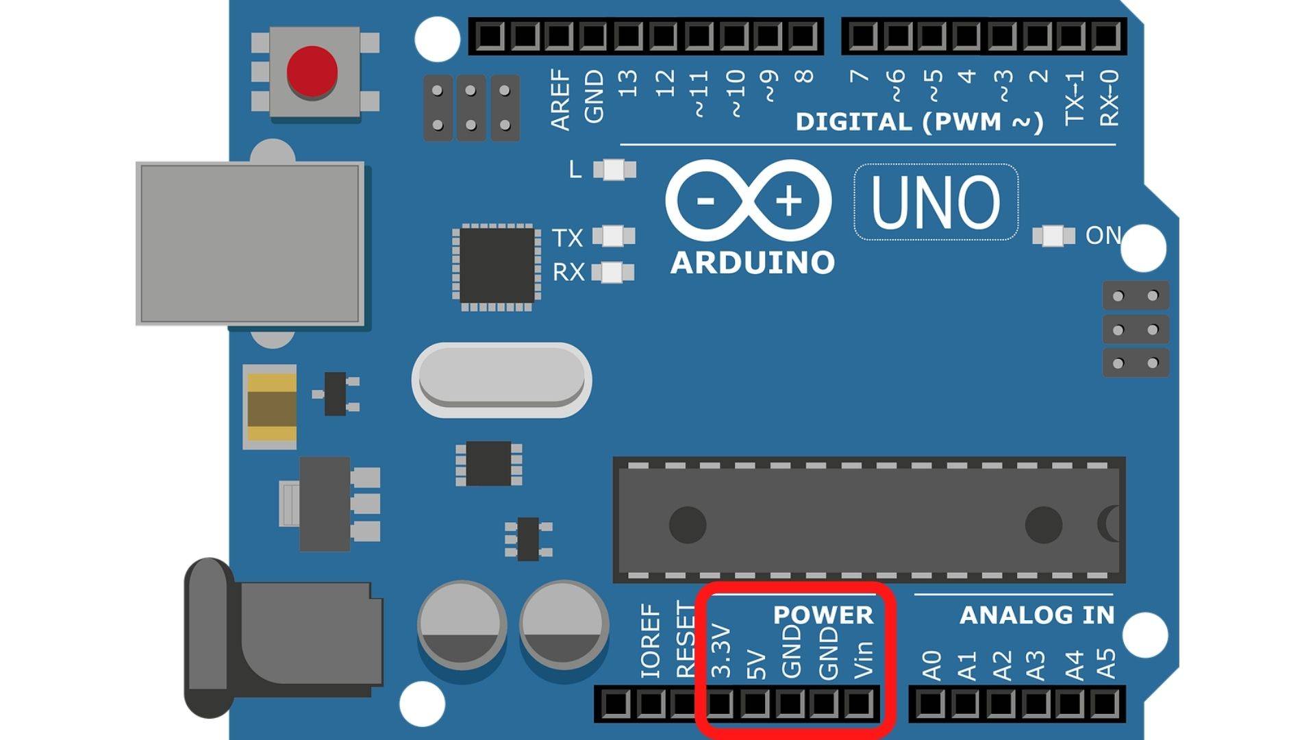
3.3V power Arduino pin
3.3V power Arduino pin: 3.3V power Arduino pin is a power supply that provides 3.3 volts of direct current to the Arduino board.
5V power Arduino pin
5V power Arduino pin: The 5V power pin is one of the power pins on the Arduino board. It provides 5 volts to power the board and its components.
VIN power Arduino pin
VIN power Arduino pin: The Vin power Arduino pin is an input voltage pin for the Arduino board. The VIN power pin provides input supply from an external power supply.
GND power Arduino pin
GND power Arduino pin: The GND power Arduino pin is essential for any electrical project. It is used to ground the circuit and prevent any mishaps with electricity. There are two GND pins on the Power Supply Pinout.
What is Pulse Width Modulation (PWM)?
Introduction
Pulse Width Modulation is a technique used in electronics to control the Output of a power supply. It is used in different applications, such as switching power supplies and dimming lights.
PWM uses analog signals to control the amount of power delivered to an electrical load. The width of the pulses( duty cycle), controls the amount of time that current flows through an electrical circuit and sets its voltage level.
Pulse Width Modulation can also control motor speed, heating and cooling, and other similar processes.
PWM Pins
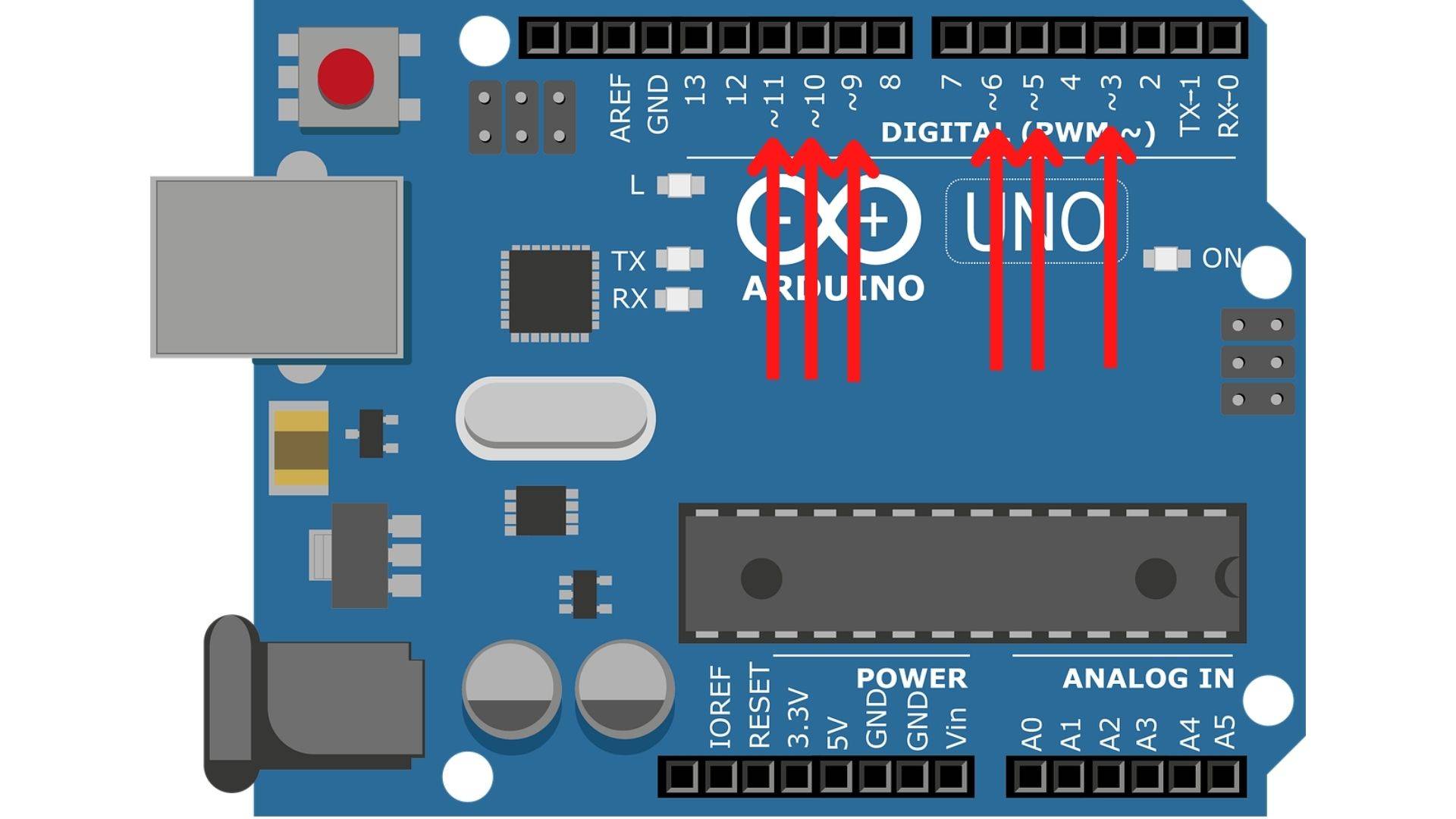
The PWM pins of the Arduino board are 3,5,6,9,10, and 11. The role of the PWM pins is to convert the digital signal into an analog one by varying the Pulse Width Modulation.
Analog Pins
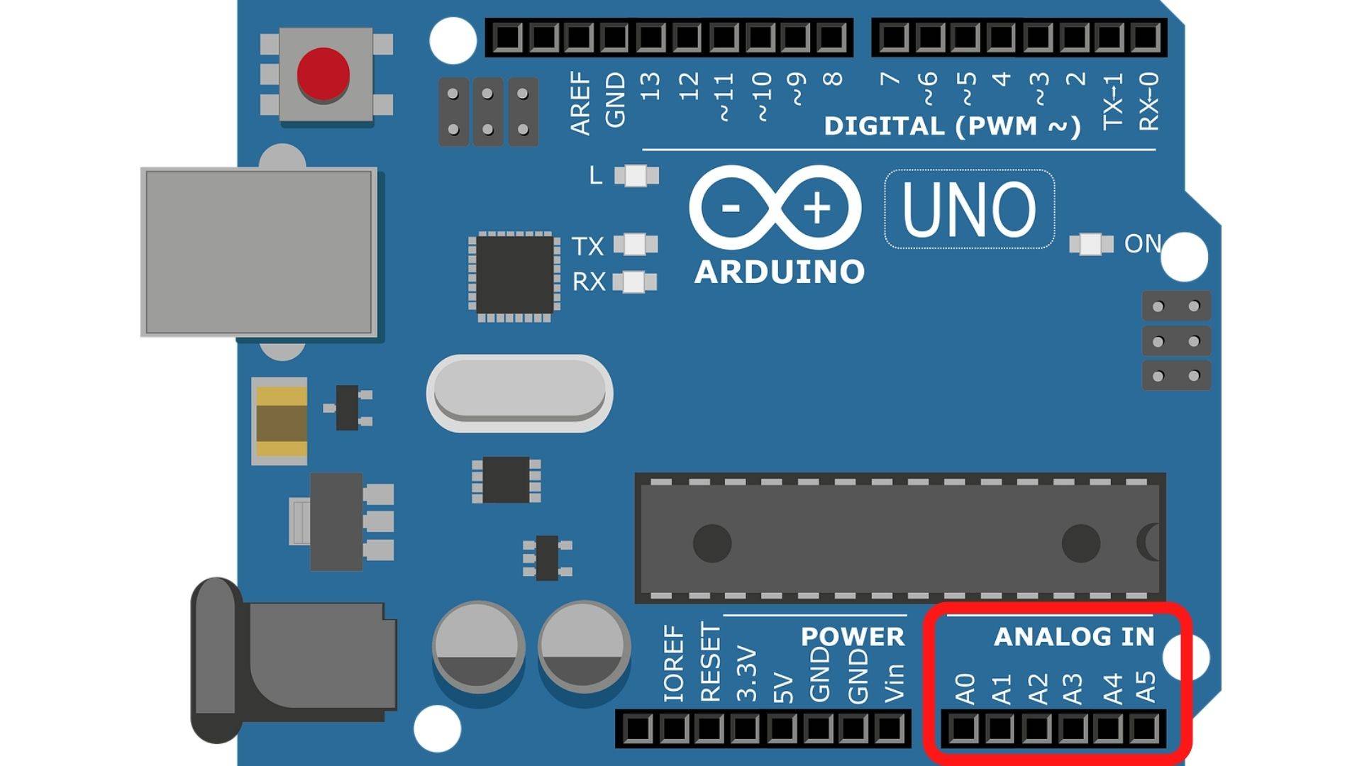
The Arduino Analog Pins are a set of digital pins that are used to provide analog signals. These pins can be used as inputs or outputs and have a voltage range of 0-5V. Arduino Pins A0-A5 are qualified for reading analog voltages.
On Arduino, the ADC has a 10-bit resolution, pointing it can represent the analog voltage by 1,024 digital levels.
Understanding the digital
Introduction
In the Arduino digital world, the voltage is represented by 0 and 1. 0 design 0V and one design 5V. Other terms used in this field are: On/Off and HIGH/LOW. Digital pins have an input or output uses:
Introduction
1.Digital pins are Output, set to 0 or 5 volts.2.Digital pins are Input, so the voltage is supplied from an external device. The voltage level is between 0 and 5 volts.
Digital Pins
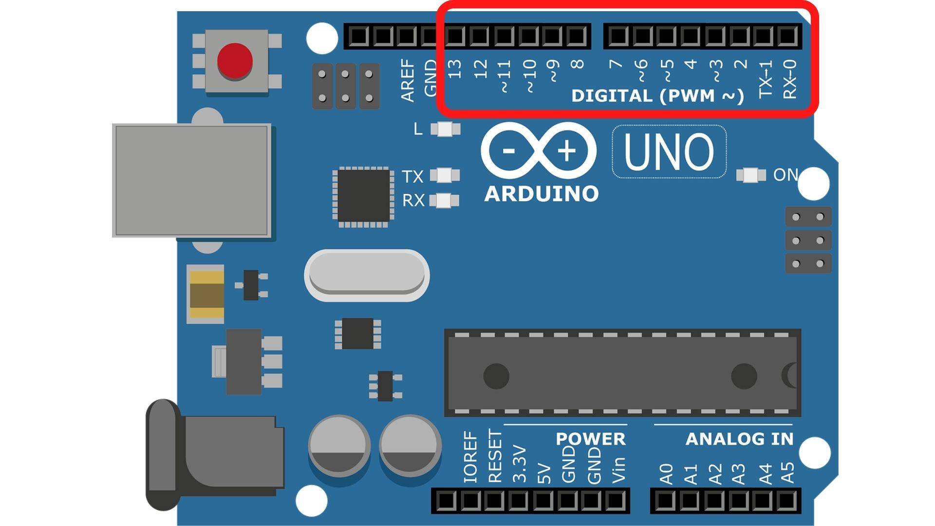
The Arduino Uno is a platform for artists, designers, hobbyists, and anyone interested in creating interactive projects. It has 14 digital input/output pins that can be used to read sensors and control outputs (The pins 0-13).
Arduino digital pins are the basic building blocks of Arduino boards. They connect sensors, motors, lights, and other components to the Arduino.
The Arduino PINS are used to control devices and make them interact with each other. The digital pins can be any of the following:
Digital Pins
Analog Input means that you can use an analog sensor or a potentiometer to measure a physical quantity like light or sound.
Digital Output means that you can use a relay, motor, or light to control another device like an LCD or motor.
Digital pin change interrupt means that you can use an interrupt pin on your Arduino board for external interrupts like when you press a button on your computer keyboard.
What are Communication Protocols?
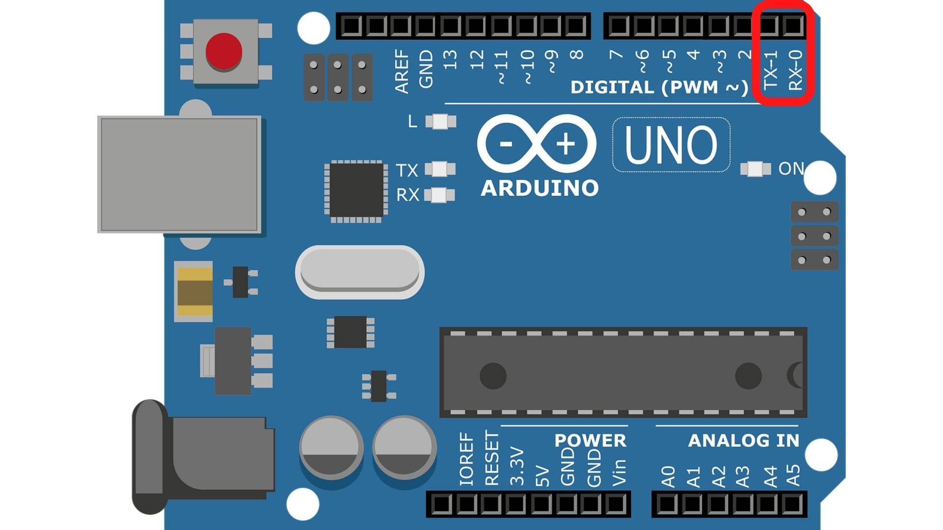
The Arduino can be programmed to do different things. It has digital pins 0 (RX) and 1 (TX). These pins are used to communicate with other complicated devices. Serial communication allows the data exchange between An Arduino board and other devices.
The transmission occurs via USB through the 0 (RX) and 1 (TX). Communication protocols allow the user to connect multiple serial-enabled devices and leave the primary serial port available for the USB.The SCL, TX, SDA, and RX are communication pins.
Aref pin
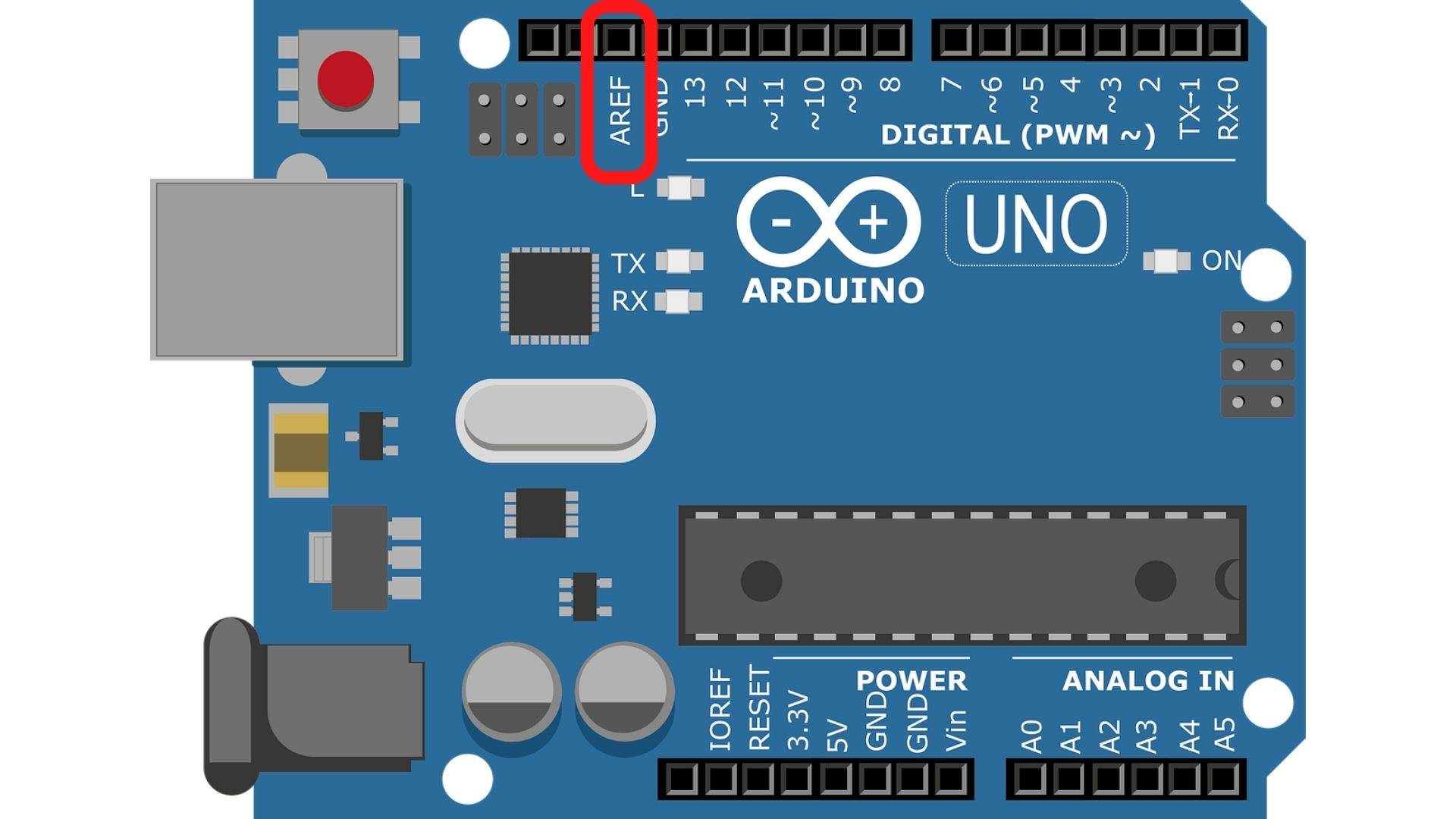
Aref pin is the Reference voltage for the analog inputs. AREF allows the programmer to feed the Arduino board a reference voltage from an external power supply to configure the reference voltage for the analog input.
SPI Pins
SPI pins are the abbreviation of the words: Serial Peripheral Interface. The pins concerned for this category are 10,11,12, and 13 of the Arduino board.
- SS: PIN 10 is for a Slave Select
- MOSI: PIN 11 is for a Master Out Slave In
- MISO: PIN 12 is for a Master In Slave Out
- SCK: PIN 13 is for a Serial Clock
TWI communication
The TWI is known as I2C. The I2C protocol applies using two lines to send and receive data.There are some pins for this mission.
- Pin A4 designates Serial Data Line (SDA): holding the data
- Pin A5 designates Serial Clock Line (SCL): offering data synchronization among the devices
LED Pin(PIN 13)
The LED pin of the Arduino board has an inbuilt LED employing digital PIN 13. The LED glows when the digital pin evolves high.
Conclusion
Conclusion
In conclusion, Arduino PINS is an excellent tool built-in Arduino board for those looking to create a project.
It allows you to connect sensors and other components with the Arduino board easily.
It is also a good tool for those just starting with programming and who want to do something fun and exciting.
